English
 Español
  Português
  русский
  Français
  日本語
日本語  Deutsch
  tiếng Việt
  Italiano
  Nederlands
  ภาษาไทย
  Polski
  한국어
한국어  Svenska
  magyar
  Malay
Malay  বাংলা ভাষার
  Dansk
Dansk  Suomi
Suomi  हिन्दी
  Pilipino
  Türkçe
  Gaeilge
  العربية
  Indonesia
  Norsk
Norsk  تمل
تمل  český
český  ελληνικά
  український
  Javanese
  فارسی
فارسی  தமிழ்
தமிழ்  తెలుగు
  नेपाली
  Burmese
  български
  ລາວ
ລາວ  Latine
  Қазақша
  Euskal
  Azərbaycan
  Slovenský jazyk
  Македонски
  Lietuvos
  Eesti Keel
  Română
  Slovenski
  मराठी
मराठी  Srpski језик


Home
>
Products > Metal Chip Briquetting Machine
>
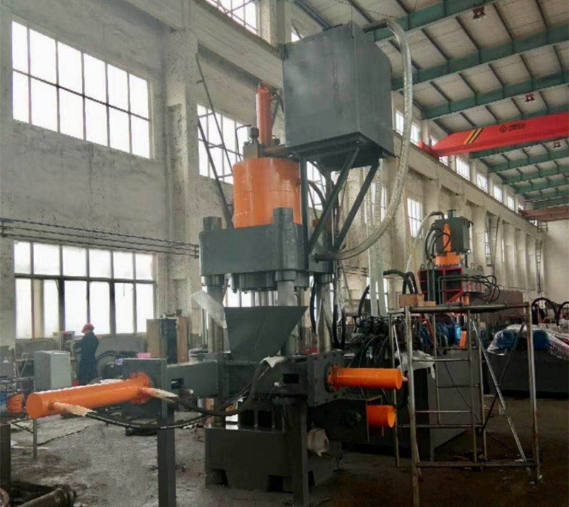
Iron filings aluminum filings cast iron filings parallel


Iron filings aluminum filings cast iron filings parallel
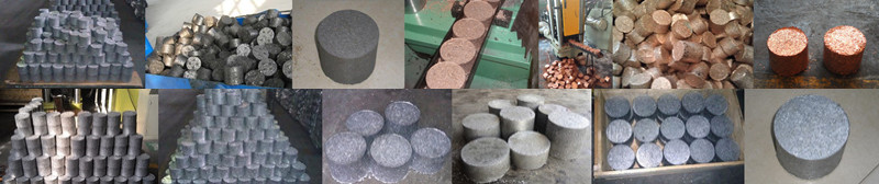
The Iron filings aluminum filings cast iron filings parallel is suitable for aluminum alloy profile plants, steel casting plants, aluminum casting plants, copper casting plants, etc. It can remove aluminum scrap, aluminum dust, steel scrap, steel slag, steel pin, iron scrap, copper scrap, copper rice, zinc scrap , Lead scrap and other briquette
Model:Y83
Send Inquiry
Product Description
Iron filings aluminum filings cast iron filings parallel Made in China
630 tons of shavings and machine
Chip and machine, chip and machine manufacturer, hydraulic chip and machine, cast iron chip cake machine, steel powder chip machine, titanium chip machine, aluminum chip machine, automatic metal chip machine, high-capacity aluminum chip machine Parallel machine. Copper pin chip parallel machine, steel chip cake machine, waste lead chip cake machine
1. Usage and characteristics
(1) Purpose
1. It is mainly used to press various metal scraps (cast iron scraps, copper scraps, aluminum scraps, etc.) into blocks through special molds, which facilitates the transportation and processing of metal scraps. It is used in steel plants, non-ferrous metal plants, and smelting. Ideal equipment for factories.
2. This machine is equipped with appropriate knives, molds and other auxiliary tools, and can also be used for correction, pressing, forming, stretching and general-purpose pressure processing where cutting and precision requirements are not high.
(2) Features
1. This machine adopts hydraulic transmission, working smoothly and low noise.
2. This machine adopts jog, single and continuous work conversion, with good automation, convenient operation and high production efficiency.
2. Overall structure and working principle
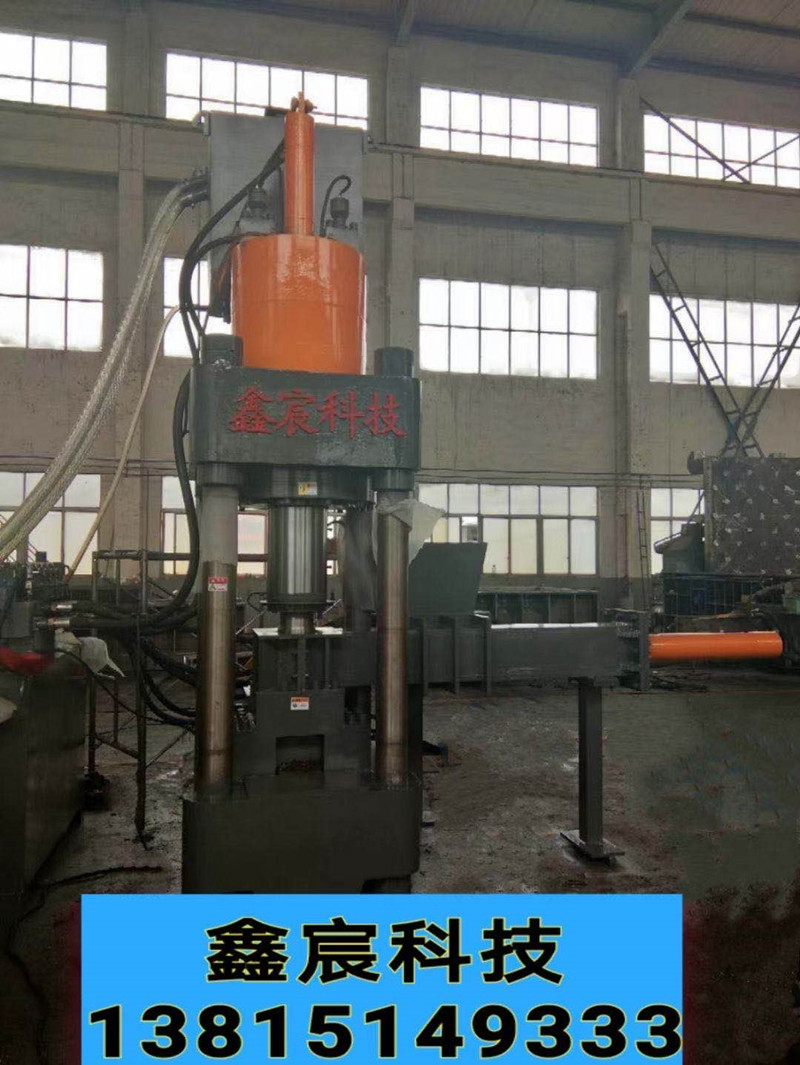
1. Overall structure The machine is mainly composed of mechanical system (main unit part), electrical system, hydraulic system, etc.
(1) The main engine is mainly composed of a main pressing mechanism and a pushing mechanism.
1. The main pressing mechanism is composed of upper beam, lower beam, upright column and material pressing cylinder. The upper beam, lower beam, and middle beam are all welded structural parts. The upper and lower beams are composed of upright columns, upright caps, and upright nuts to form the main frame of the mainframe. The pressure oil cylinder is a front flange structure and is fixed on the upper beam. The piston rod of the material oil cylinder is connected with the upper die by internal threads, and the upper die is driven by the oil cylinder to move up and down linearly. The pressure oil cylinder is a combined oil cylinder, which is composed of a piston-type single-acting main pressure oil cylinder and a quick work-in oil cylinder. The quick work-in oil cylinder is a piston-type double-acting oil cylinder with pistons, guide sleeves, etc., and a sealing ring. The lower beam doubles as a working platform, equipped with auxiliary molds and pushing cylinders.
2. The pushing mechanism is composed of a pushing cylinder and auxiliary molds. The pushing cylinder is a piston type double-acting cylinder, which is fixed on the lower beam of the main machine with a front flange structure, and the front end is connected with the ejection pad of the auxiliary mold. The auxiliary mold is composed of an upper mold, a lower fixed mold base, a mold release pad, an inner mold sleeve, a lower mold pressing plate, and a feeding hopper. The upper mold is connected to the material pressing oil cylinder with external threads and the piston rod uses the material pressing oil cylinder to move up and down to compact the material in the inner mold sleeve. The lower fixed mold base is fixed on the lower beam with screws, and a surface-treated wear-resistant inner mold sleeve and die pad are installed in the middle, and the inner mold sleeve is fixed in the lower fixed mold base with a molding plate (see the attached mold structure diagram).
3. The hydraulic oil cylinder is composed of a material pressing oil cylinder and a material pushing oil cylinder. The pressure oil cylinder is composed of a main pressure oil cylinder and a quick work feed oil cylinder. The main pressure oil cylinder is a piston single-acting oil cylinder and also adopts a piston structure. Except for the front cavity without oil, the structure is the same as the fast work feed oil cylinder and the push oil cylinder Consistent. The quick-working oil inlet cylinder and the pushing oil cylinder are both piston-type double-acting oil cylinders. The piston is equipped with a sealing ring to form two oil chambers in the cylinder. When the high pressure oil acts on the rear cavity (also known as the large cavity) or the front cavity (Also known as small cavity) when pushing the piston to make a straight reciprocating motion in the cylinder, to achieve the purpose of driving the moving parts. At the same time, the cylinder port is provided with a guide sleeve for supporting, guiding and sealing the piston rod.
(2) The electrical system is composed of two parts: a motor control circuit and an action control circuit.
(3) The hydraulic system is composed of oil tank, pump station, valve station, etc. The main engine is divided into two parts: the feed oil circuit and the main pressure oil circuit.
2. Working principle
Add the material to be processed from the hopper to the lower mold inner mold sleeve, press the automatic button, the upper mold will compress the material down to the system set pressure and return for 1 to 2 seconds (set by plc) to unload, and the pusher cylinder returns When it is in place, the upper mold moves downward to extrude the metal chips in the inner mold sleeve out of the mold cavity and returns, and the push cylinder advances to push the compact out of the mold cavity, completing a work cycle.
Four, electrical system
(1) Overview It is powered by a 380 volt AC power supply and consists of two parts: the main circuit and the control circuit.
1. The main circuit is composed of two parts: the motor circuit and the emergency stop circuit, which is powered by a 380V power supply. The motor circuit directly supplies power to a y-type three-phase asynchronous motor from the circuit power supply to drive a plunger pump and a gear pump. The emergency stop circuit consists of an emergency stop button and intermediate relay. In the event of an accident, just press the emergency stop button to stop the motor and interrupt all actions.
2. The control circuit is composed of two parts: a motor control loop and an action control loop (also called plc input and output loop). The motor control circuit is composed of motor start, stop and motor work display, etc. The action control circuit is composed of the forward and backward movements of the main pressure cylinder and the forward and backward movements of the pushing cylinder, which are mainly used to control the mechanical work.
(1) Polymer circuit breaker qf model dz47-80 (80a) power control, used to cut off and switch on system power.
(2) Motor m model y220l2-4, power 22kw, speed 980r/min, double output shaft is used to simultaneously drive an axial piston pump and a gear pump.
(3) Button sb1 model la18-22/220v motor to stop
(4) Button sb2 model la18-22/220v motor start
(5) Control transformer tc model bk-250/380/220v control loop power control
(6) Intermediate relay ka model cjx1-12/220v emergency stop control
(7) Stroke switch sq model jlxk1-411 stroke control
(8) Indicator light hl model slc22 power indicator, motor working indicator, fault display
(9) AC contactor km model cjx1-63/380v motor control
(11) Transfer switch sa model psc22-d jog, single, continuous conversion
(12) Valve solenoid yv model mfb1-5.5yc action reversal control
(13) Programmable controller plc model cpm1a-30cdr action control
(14) Emergency stop button sb model pbc22-c emergency stop
(2) Description of electrical principle
1. Switching on and off the power supply is realized by the high breaking circuit breaker qf.
2. Motor start and stop (star-delta start control)
Turn on the power, the power indicator hl is on; press the motor start button sb1, the button is normally open touch
When the point is closed, the coils of the AC contactors km1 and km3 are energized, and the normally open contacts are closed to continuously supply power to the coils. The main contacts of the AC contactor km1 are closed and the motor is energized. After a delay of 3s, the AC contactor km2 is energized and km3 is de-energized. The motor enters the normal working state; the signal light hl2 is on, indicating that the oil pump is working normally; press the motor stop button sb2, the normally closed contact is disconnected, the AC contactor coil is de-energized and the normally open contact is disconnected, the main contact is disconnected, and the power supply is cut off , The motor m stops when the power is cut off,
Hot Tags: Iron filings aluminum filings cast iron filings parallel, Manufacturers, Suppliers, Customized, China, Made in China, Second hand, Quality, Advanced, Durable, Easy-maintainable
Product Tag
Send Inquiry
Please feel free to fill your inquiry in the form below. We will reply you in 24 hours.